
Back to my bench!
Let's meet a rare girl: the Sherman M4A2 - T10 Mine Exploder (M4A2 T10).
Let's meet a rare girl: the Sherman M4A2 - T10 Mine Exploder (M4A2 T10).
Land mines are explosive apparatus installed concealed under or on the ground and designed to destroy or cripple enemy targets ( animals, men,vehicles or tanks...), as they pass over or near them. They typically explode automatically by pressure when a target walk or drive on them, although other detonation triggers are also sometimes used.

The land mines may cause damage by direct blast effect, by shrapnel or by both. To increase their effectiveness, landmines (personal and/or anti-tank) are generally installed in large numbers in an area called minefield. In military science, minefields are considered a defensive or desabling weapon, used to slow the enemy advance, to interdict certain terrain to the enemy, to direct the enemy into kill zones, or to reduce the morale, affecting randomly equipment and personnel. In some battles during World War II, anti-tank mines accounted for half of all vehicles disabled.
Since combat engineers with mine-clearing equipment can clear a path through a minefield relatively quickly, mines are usually considered effective only if covered by fire.
 |
| German minefield |
During the planning for D-day, a rapid means of clearing the extensive minefields expected in Normandy was considered essential for the success of the Invasion. As for the other types of specialized armor, the development of such equipment and its associated tactical doctrine was assigned by the British to their 79th Armoured Division.
One early mine clearing device was the rotary flail consisting of a cylindrical rotor with chains attached. When rotated, the chains beat the ground ahead of the vehicle in the hope of detonating any mines at a safe distance. The early flails (Scorpion devices) fitted to the British tanks Matilda and Valentine were unreliable, but they were improved with further development. The Sherman Crab can be considered the apex of this development.
 |
| Matilda Scorpion mine flail tank |
 |
| Valentine Scorpion mine flail tank prototype |
 |
| Sherman Crab mine flail tank |
In United States, the early work of the Ordnance Department on mechanical exploders concentrated on roller type equipment. The first of these was the mine exploder TI fitted to the M3 medium tank. It consisted of two large rollers pushed in front of the tank with one ahead of each track. Each roller was assembled from four heavy steel discs 1 meter in diameter spaced apart on a central shaft. A third roller of five such discs was towed at the center rear of the tank to give complete path coverage.
 |
| TI mine exploder fitted to the M3 tank |
 |
| TI mine exploder fitted to the M3 tank - side view |
American Mine Exploders/Excavator "T" series:
- Mine Exploder T1E1 (Earthworm): Disks made of armor plate. Saw limited use.
- Mine Exploder T1E2: Disc roller being reduced to 2 forward units each with 7 discs. Experimental only.
- Mine Exploder T1E3 (M1) "Aunt Jemima": Two roller units each of 5 10' steel discs. 75 built. Used in Normandy and Italy. Most widely used mine exploder. Sometimes a 2nd tank was used to push it.
- Mine Exploder T1E4: Developed in 1944 with 16 discs pushed in front.
- Mine Exploder T1E5: Developed in July 1944 based on T1E3 but with smaller wheels. Experimental only.
- Mine Exploder T1E6: As T1E3 but with serrated edges to discs. Experimental only.
- Mine Exploder T2E1: Similar to T2 used on M3. Developed for US Marine Corps. For use with Tank Recovery Vehicle M32 utilizing the boom. Proved impractical and abandoned in Oct 1944.
- Mine Exploder T2 Flail: American designation for British Crab I equipment. Small number used by US Army in NW Europe.
- Mine Exploder T3: Based on British Scorpion. Proved unsatisfactory and development stopped in 1943.
- Mine Exploder T3E1: T3 rebuilt with longer arms and sand filled rotor. Proved unsatisfactory and cancelled.
- Mine Exploder T3E2: T3E1 with rotor replaced by steel drum of larger diameter. Terminated at wars end.
- Mine Exploder T4: British Crab II.
- Mine Excavator T4: Plough device developed in 1942. Impractical and was abandoned.
- Mine Excavator T5: Like T4 but plough was v shaped. Modified version of this was designated T5E1.
- Mine Excavator T2E2: Late 1943 was modified T5E1 with arms and hydraulic lift gear from the M1 dozer so plough could be raised or lowered.
- Mine Excavator T6: Design based on v shaped plough. Unsatisfactory due to inability to control depth.
- Mine Excavator T5E3: Angled plough was mounted on front of M1 dozer assembly.
- Mine Exploder T7: Late 1943, consisted of frame carrying small rollers each made of 2 discs. Unsatisfactory and abandoned.
- Mine Exploder T8: Steel plungers carried on a pivoted frame. Beat up and down on the ground as vehicle moved forward. Steering was adversely affect. "Johnnie Walker"
- Mine Exploder T9: Six foot roller. Difficult to maneuver.
- Mine Exploder T9E1: Lighter T9 but unsatisfactory as sometimes failed to explode mines.
- Mine Exploder T10: Remote controlled mine exploder vehicle based in M4A2 chassis with a tricycle unit placed under tank and controlled by following tank. Unwieldy and cancelled.
- Mine Exploder T11: With 6 mortars to fire forward. Experimental only.
- Mine Exploder T12: 23 mortars. Proved effective but was cancelled.
- Mine Exploder T14: M4 tank with added belly armor and heavy duty tracks. Cancelled at war end.
The Sherman T10 Mine Exploder:
In the beginning of 1944, the NDRC (National Defense Research Committee) designed a self-propelled mine exploder using two large (244cm in diameter) power driven wheels mounted on a common shaft, that was to be wire-guided from an armored vehicle following in the cleared path. Heavy steel discs were loosely mounted on the shaft allowing articulation when moving over rough ground. Thus they would explode any mines between the two wheels. A long trail extended behind the exploder assembly to a third wheel in the rear. Referred to as the Tricycle, plans called for the installation of an engine in each large wheel. Tests were run at Aberdeen in late 1943 using just the wheel and trail assembly without the engines or the loose center discs.

The exploder proved effective, but an operational perspective, field-changing an expendable wheel would be much easier, faster, and less expensive than replacing a far more complex self-powered wheel. This unorthodox complication was fortunately dropped in favor of a more practical approach when the Tricycle concept evolved into the T10 Mine Exploder. Prototyped by the Fisher Body Division of General Motors in Grand Blanc, M1, the pilot vehicle was an adaptation of the Sherman M4A2 large hatch/ high bustle turret.
The tank body was stripped of its tracks and running gear so that its front-mounted differential could be coupled (through a projecting pinion gear) to the oversize slotted wheels. The M4A2 high bustle turret with its 75mm gun was operationally retained, though presumably of no tactical use when the vehicle was remotely operated.

The exploder proved effective, but an operational perspective, field-changing an expendable wheel would be much easier, faster, and less expensive than replacing a far more complex self-powered wheel. This unorthodox complication was fortunately dropped in favor of a more practical approach when the Tricycle concept evolved into the T10 Mine Exploder. Prototyped by the Fisher Body Division of General Motors in Grand Blanc, M1, the pilot vehicle was an adaptation of the Sherman M4A2 large hatch/ high bustle turret.
 |
| font: http://the.shadock.free.fr/sherman_minutia |
 |
| font: http://the.shadock.free.fr/sherman_minutia |
 |
| M4A2 T10 mine exploder - side view |
| M4A2 T10 under transport with normal VVSS suspensions Notice the mine exploder wheel in the rear (red arrow) font: http://the.shadock.free.fr/sherman_minutia |
| M4A2 T10 under transport with normal suspensions - rear view Notice the high bustle turret (green arrow) and rear wheel T10 support (red arrow) font: http://the.shadock.free.fr/sherman_minutia |

 |
| T10 "early version: Notice the absence of the "cleaning stars" acting on the rear wheels gaps. The mud turns the discs into a large cylindrical wheel. The front wheels shows transverse claws to increase traction, but the mud fills everything... Compare a photo above with an improved version below |
| T10 "late version" - Rear left view - Notice the "stars" which removed the mud from the spaces between the wheels ... |
| T10 "late version" - Rear right view |
| T10 "late version" - Notice the "stars" which removed the mud from the spaces between the wheels ... |
Tested at Aberdeen in May-June 1944, the T10 was considered unsatisfactory. Captain Merritt D. Elliott reported "The vehicle, to date, has not been too successful due to the fact that only the front two rollers are powered, and the rolling resistance of the rear roller, which is unpowered, tends to cause the vehicle to get stuck." Perhaps with his tongue in cheek regarding the outlandish appearance of the tank, Elliott wrote, "From all indications, it seems the Ordnance Department is making any and every kind of device to remove mines."
Even if the usual development problems had been solved, its great weight and slow speed would have limited its value in combat.
Specs:

| M4A2 T10 Mine Exploder | |
|---|---|
Type
|
Mine exploder tank
|
Place of origin
|
USA
|
Service history
| |
In service
|
prototype (1944)
|
War
|
World War II
|
Production history
| |
Designed
|
1940
|
Manufacturer
| Fisher Body- Division of General Motors |
No. built
|
1
|
Specifications
| |
Weight
|
52.800 Kg
|
Length
|
8,74 m
|
Width
|
3,81 m
|
Height
Ground clareance
|
3,58 m
1.410mm
|
Crew
|
remoted controled or 5 (commander, gunner, loader, driver, co-driver)
|
Armor
|
93 mm (3.7 in) effective against 7.5 cm APCBC with cast glacis
118 mm (4.6 in) effective against 7.5 cm APCBC with 47° RHA glacis
|
Main armament
|
75 mm M3 L/40 gun (90 rounds)
|
Sec. armament
| |
Engine
| |
Power/weight
|
6,6 hp / metric ton
|
Suspension
Fuel capacity
|
2 front wheels and 1 rear wheel
560 liters
|
Operational range
|
241 km at 560 L; Diesel
|
Speed
|
11 km/h
|
The kits:
For this project, I'll use the Sherman T10 Mine Exploder from Bolddivision ...
 |
| Bolddivision box kit a very strong cardbox |
The Bolddivision recommends using a Tamiya M4A3 (#35250) as a kit donor parts, but I will use an M4A2 Sherman US Marines from Academy (#13203).
 |
| Academy's M4A2 Sherman US Marines (#13203) |
As the original vehicle was derived from a late M4A2, I will follow the Fisher Arsenal specifications !!
Resin parts are finely cast and there are still laser cut styrene parts. All nicely packaged in a thermo-nuclear explosion proof box ... 185 parts in total... No PE or decals.
 |
| All parts in styrene plastic and resin |
 |
| In my workbench... |
The instruction booklet is 4 sheets of A4 paper with spartan instructions in German and English, with 10 steps. The strange thing is that the instructions "end" before the kit is finished. There is no drawing showing the positioning of the chassis with the upper hull ... Odd ...


 Well...Let's start... First of all, a question: the BoldDivision kit comes with upper hull in resin. This hull is based in a M4A3 Tamiya hull with M4A2 rear deck. But the hull is solid, very heavy...and this worries me a lot. Looking at the pictures of the pieces, the rear fork seemed to me to be fragile to support the weight of the solid model. I imagined this piece "buckling" with time, because the resin is very "plastic" and soft.
Another detail is that BoldDivision recommends as a "host" kit an M4A3 Tamiya (perhaps for a perfect marriage between the upper hull and the chassis of the host kit ...).
But the original vehicle was an M4A2 ... and the Tamiya chassis does not have the details of the lower chassi and rear plate and exhausts of an M4A2, but an M4A3. Because of these details, I decided to use BoldDivision's excellent upper hull as a template and make my own set of upper hull + chassis, in plastic. As I had the two kits in question (the M4A3 Tamiya and the M4A2 Academy...) I decided to compare them:

I used the excellent hull of BoldDivision as template for my surgery...


Well...it's painting time... And I hate vehicle without markings... I thought about making operational markings on the T10. I started researching in the (excellent) book Son of Sherman, especially the serial numbers.


Another detail is that BoldDivision recommends as a "host" kit an M4A3 Tamiya (perhaps for a perfect marriage between the upper hull and the chassis of the host kit ...).
But the original vehicle was an M4A2 ... and the Tamiya chassis does not have the details of the lower chassi and rear plate and exhausts of an M4A2, but an M4A3. Because of these details, I decided to use BoldDivision's excellent upper hull as a template and make my own set of upper hull + chassis, in plastic. As I had the two kits in question (the M4A3 Tamiya and the M4A2 Academy...) I decided to compare them:
 |
| The BoldDivision resin kit, the Tamiya and the Academy upper hulls... Notice the similarities and differences between them ... |
What bothered me the most was using the M4A3 Tamiya chassis, with no details of the original version. I'm not a "rivet counter", but that's frustrating ...
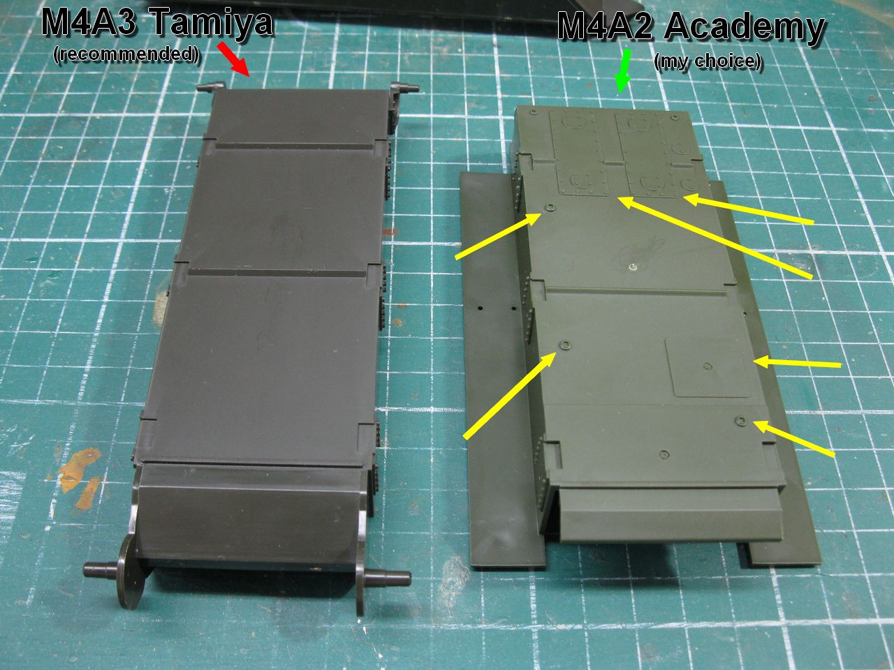 |
| Notice the "poor" Tamiya's chassi and the Academy one... Big differences here... |
But the upper hull of the Academy was not perfect: Notice the circular weld marks on the region of the front machine gun in the actual T10. The Tamiya presents this detail, but the Academy kit does not !!!
Damn!!!
 |
| Damn weld marks!! |
My Solution: Use the best of both worlds: Transplant the Tamiya glacis to the upper-hull from Academy... Surgery time !!! Using scalp, I cut at the internal angles of the glacis, until complete separation; patience and sharp blades ...
 |
| Removing the best detailed glacis from an upper hull I do not want ... |
Repeating the process in the upper hull of the Academy: working carefully not to damage the pieces ...
 |
| Removing the bad glacis from the better upper-hull... |
And gluing the glacis Tamiya (with the right details ...) in the upper-hull Academy, with full compatibility with the M4A2 Academy chassis
 |
| My Precious!! |
How I hate waste and love build rare and odd things, let's recover the upper-hull Tamiya. Who knows, it will work for a future-new project ?? !!
 |
| A new guest for my spare-parts box!!! |
Another detail that bothered me a lot was the shape of the rear armor: The upper-hull Tamiya (and the BoldDivision part ...) have a very angled rear plate, totally different from the almost perpendicular rear plate of the real M4A2.

 |
| The Academy's rear plate: Same angle as the actual vehicle ... |
 |
| Comparative differences between them. |
The results really made up for the work (which was not much ...): The final resilt was this hybrid hull: The best of worlds between BoldDivision, Tamiya and Academy.
 |
| My girl!!! A perfect match between historic-correct upper-hull and chassi |
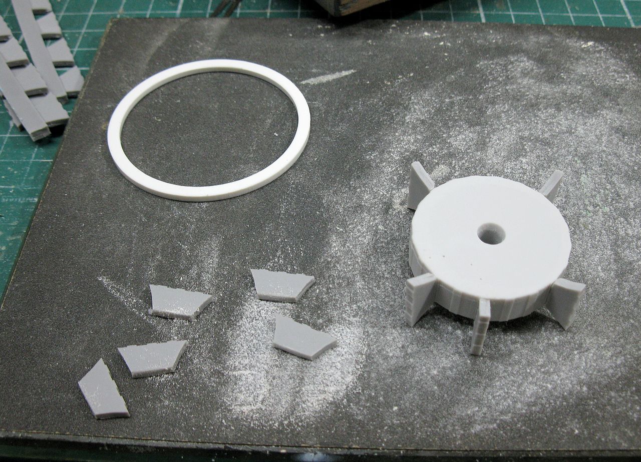
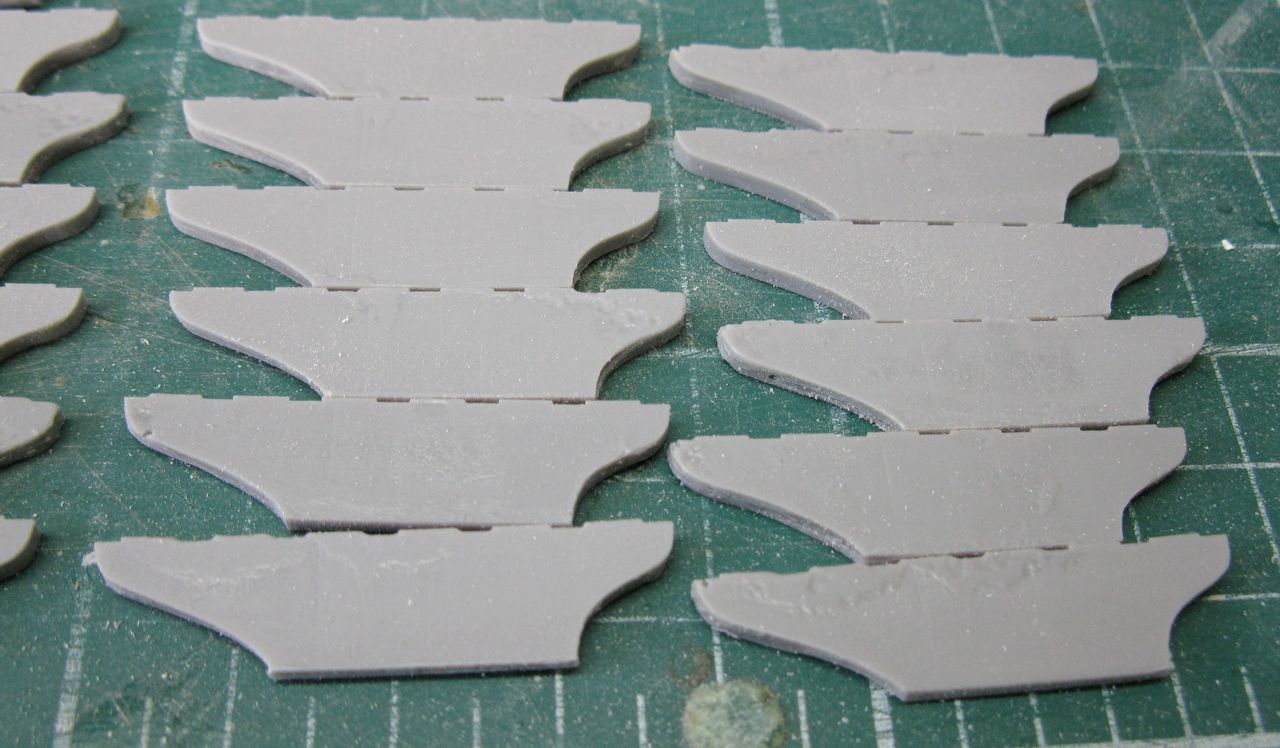
Uff... After this session of surgeries and transplants, let's follow the booklet: build the wheels. rear wheels first !! I confess that I trembled with fear at seeing the pieces and the form of assembly; my brain said; will give a damn trouble in the end !!! By the book, cutting and cleaning the resin parts!!!
 |
| Removing parts from cast bar... Grooving the two sides of the piece with scalpel ... |
 |
| After grooving, it is only to force the piece from one side to another... that it breaks in the region previously cut ... Easy and clean !!! |
After a small sandpaper in the cut region, we glued with super glue. I used one method to paste one piece yes and another not, to facilitate the access of the fingers ...
 |
| Glueing the "spokes" of the wheel |
And the final results!! The intermediate spokes were positioned with the aid of a tweezer ...
 |
| Done!! |
The introduction of the "solid tires" was a bit more complicated, but I litched the "teeth" in the spokes a little and scraped the sharp edges of the inner portion of the tires with the scalpel, rounding these areas: this facilitated (and very ...) the introduction of the tires into the spokes. Congratulations on engineering, BoldDivision... Very good precision in one piece with so many variables that could go wrong ...
 |
| I was expecting a storm ... It was a refreshing drizzle !!! |
 |
| The two rear wheels ready for action!! |
I like to alternate between the problems. So that the building is not tiring and is the most fun possible ... Since I had just passed through a delicate phase of resin, let's delight in the plastic ... and the best of its forms: the scratch!
 |
| Planning chassis cuts |

 |
| I love my Dremmel and my saw tool. But this tool is very, very dangerous!!! |
 |
| Surgery done!!! Heart beat returning to the normal ... |
 |
| Pretty!! |
 |
| Side view!! |
 |
| Dry-fit with BoldDivision drive sprockets... Ok!!! |
Now, let's close the armour that was cut, with plasticard plates !!
 |
| Armoured, again!!! |
 |
| Upper hull and chassi perfectly fitted!!! |
 |
| The resin part and the plastic Frankenstein!!! |
And to de-stress, let's ride the main wheels; same method of the rear wheels, only in more quantity !!! Assembly line: removal and cleaning of ALL parts for later sequential assembly ...
 |
| Gentlemen, start your engines!!! |
 |
| The spokes... Notice the shapes in correct position... |
 |
| Using super-glue : one yes, one no... |
 |
| Five minutes later. Belive me...five minutes!!! |
 |
| Wheels!!! |
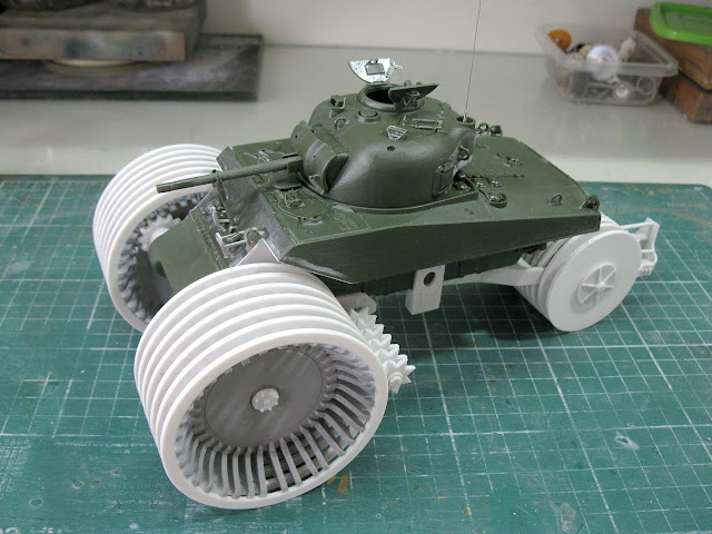
Following the "Panzerserra Mounting Alternation Law", we will mix resin with plastic: testing the position of the cleaning device in the chassi.
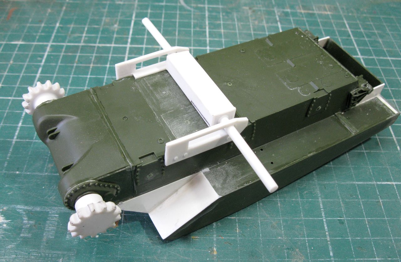 |
| The main cleaning device in dry-fit. Ok!! |
Bolddivision provides a high quality styrene tube as its main axis. but as I am traumatized with deforming kits with weight, I found in my scrap case an axle of the same thickness in aluminum. Hallelujah!!!
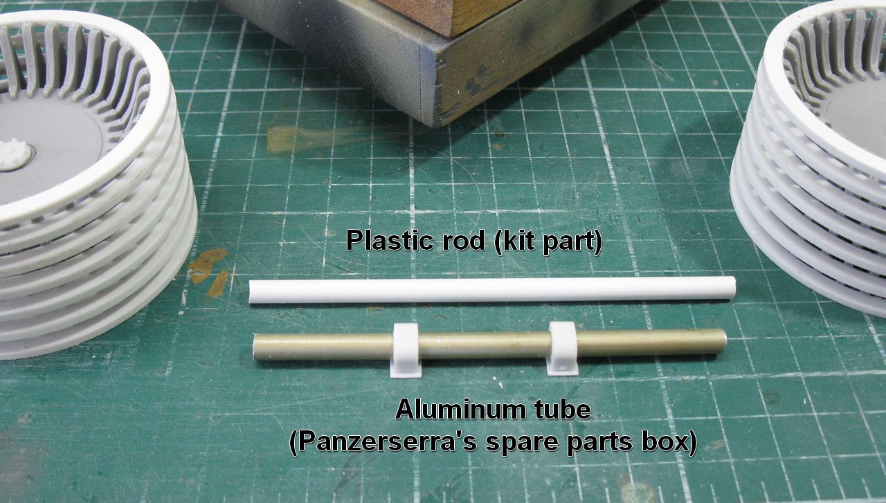 |
| A strong change!!! |
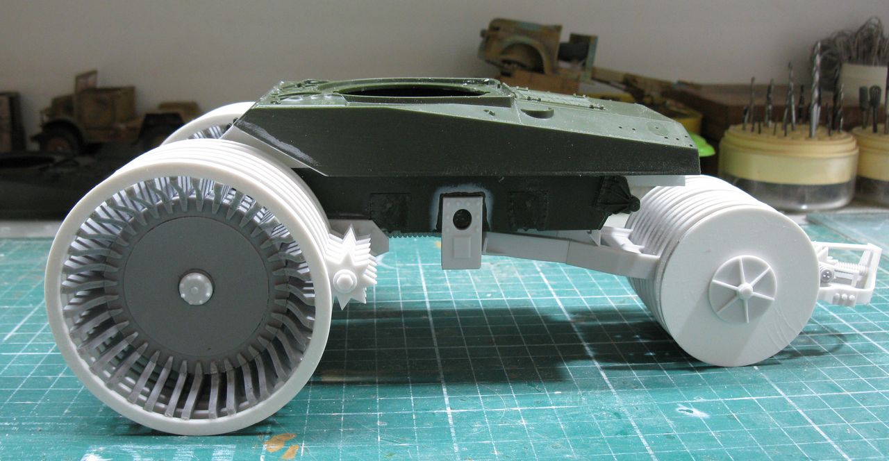
´ After testing and testing the main wheels in position, I came to the conclusion that the bases of the main shaft bearings should be 3mm higher so that the front wheels fit perfectly on the drive sprockets and the hull. I put two 1.5mm thick pieces on the bearing bases and voiláá!!
 |
| Placing shims on the bearings |
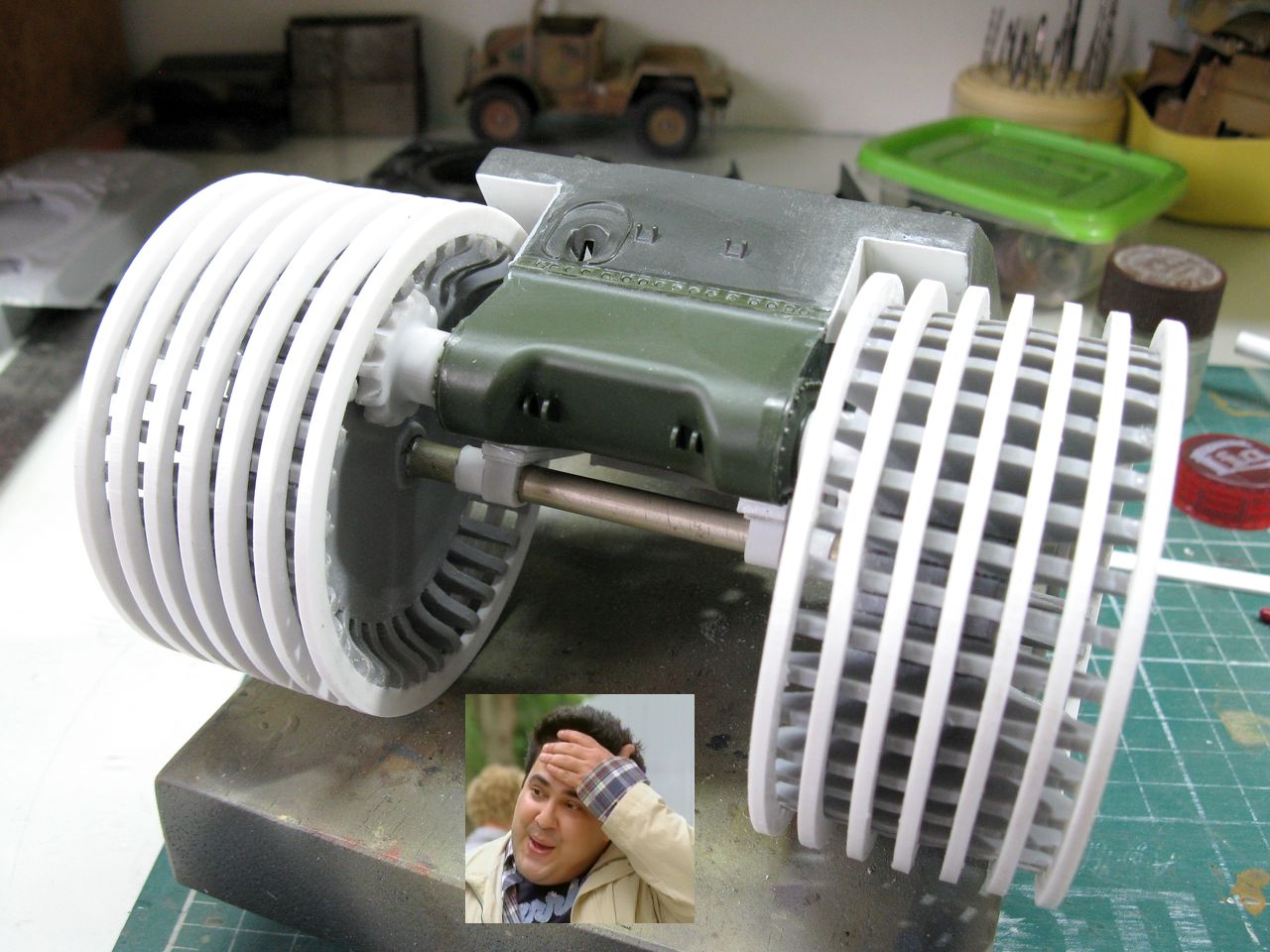 |
| And everything fits the bill !! |
 |
| Front wheels in position. Down and locked!! |
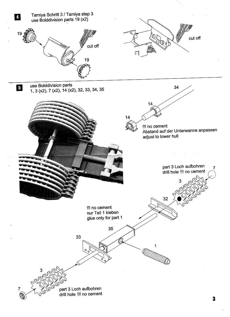
And now, a criticism for BoldDivision: the instructions for building the rear fork are confusing and conflicting... A drawing shows a sequence ... The drawing on the next page shows another different and uff ... It was the most difficult part to build. Please, please review these graphics ...
 |
| The rear fork: a true nightmare!! |
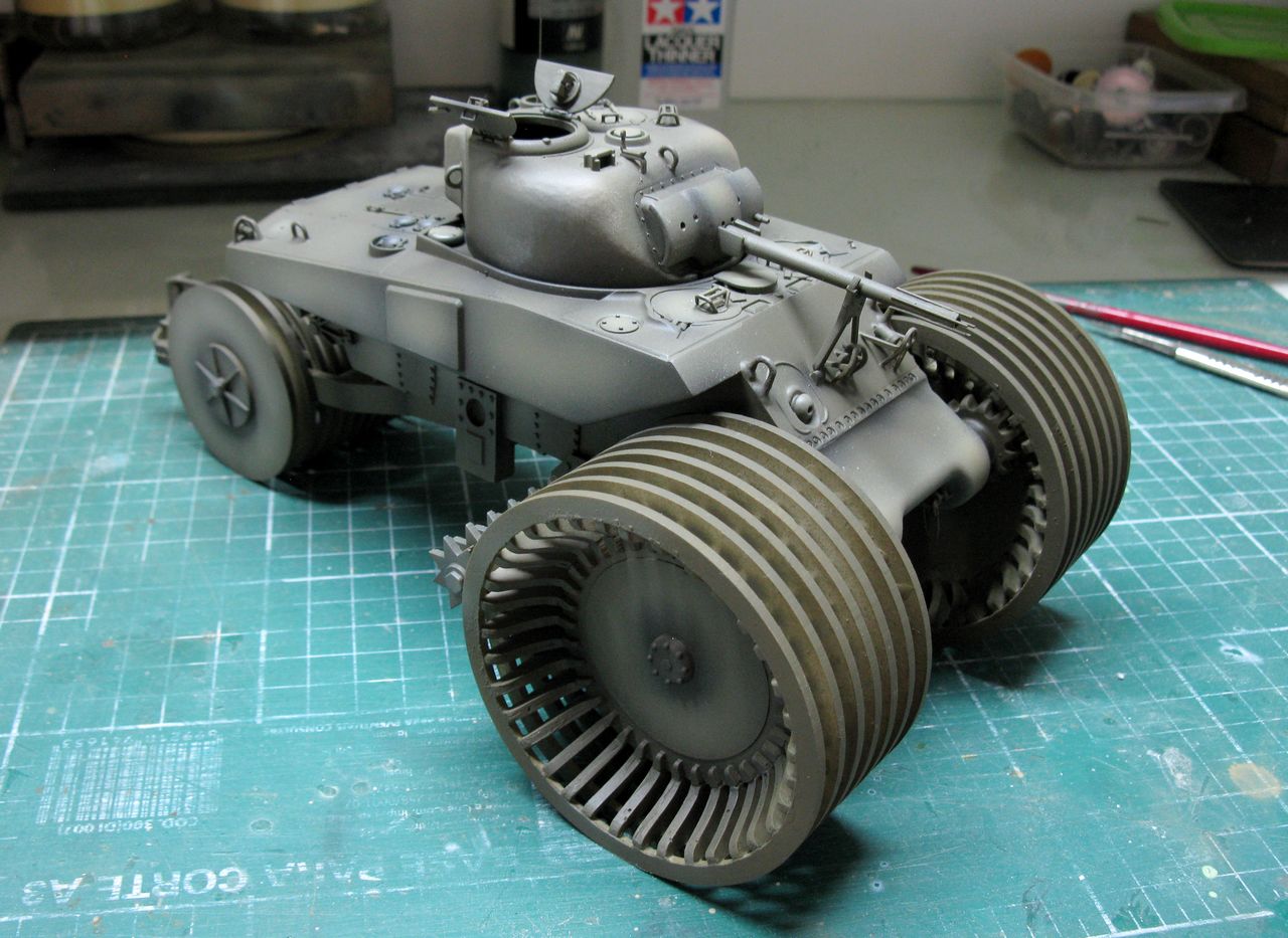
But let's finish the assembly, now:
 |
| The girl, on your own feet. |
 |
| Awesome vehicle!! |
 |
| The real stuff... |
 |
| With Kojak, for size comparison... |
Well ... I needed a grille for my exhausts. As neither the Tamiya kit nor the Academy kit has this piece, I decided to cut from the upper hull of Bolddivision: one last transplant in this our Frankenstein !!!
 |
| Again, the "Vicious Dremmel Saw" in action... |
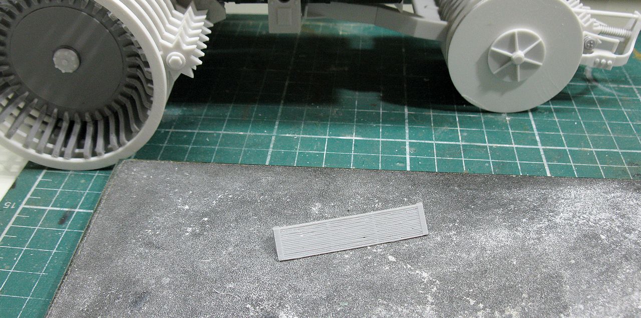 |
| The rear grille in my sand-plate... |
 |
| And in position!!! |
The steps of plastic detailing, I did not photograph (sorry ... it was the rush ...) but it was simple, routine work, following the Academy's manual. The positioning of the front headlight and the siren were based on the photos that are part of the historical review of the vehicle, just above.
 |
| Almost there... |
 |
| Cute, is not it ??? |


In photos of the rear view of the T10, I discovered this device, which seems to me to be a rear wheel height adjuster, which is not part of the Bolddivision kit. I did in scratch a free interpretation on this apparatus ...


Well...it's painting time... And I hate vehicle without markings... I thought about making operational markings on the T10. I started researching in the (excellent) book Son of Sherman, especially the serial numbers.
 |
| Sherman's new bible!! |
And I got the markings and decals with what I wanted:
 |
| M4A2 (75) Fisher Tank Arsenal - request n. T-4340 (1944) My girl: 3080381 |
 |
| M4A2 (75) FTA - USA 3080381 - Very plausible ... |
Olive drab. My first experience with AK primer... Hmmm.. so, so...


And my girl: M4A2 (75) FTA - 3080381: the glossy aspect is the Future, to prevent silvering...


Weathering:


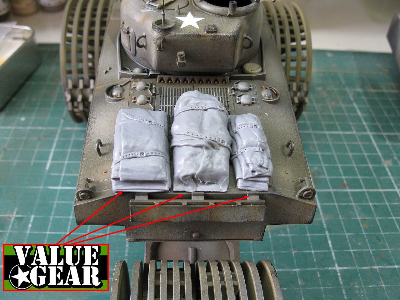
As I decided to make my girl with operational markings, let's put some stuff on the rear deck: Value Gear: Always a great request !!!
Some more operational details: put the steel cable (green arrow) and remove the protection of the gun and add the .30 in the front glacis (red arrows) !!!

Well...While I was studying about minerollers, I came across this photo ( in this awesome book of Steve Zaloga) of an Aunt Jemima in the winter ... and noticed Shermie's rear deck: an Allied air recognition panel!!
And I asked myself: Why not make one ??

Aluminum foil and paper-tape: easy!!!

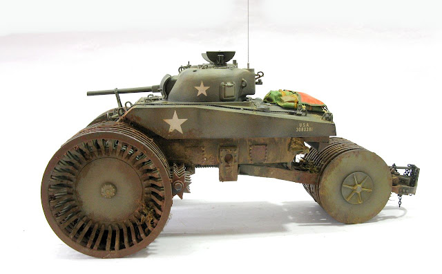
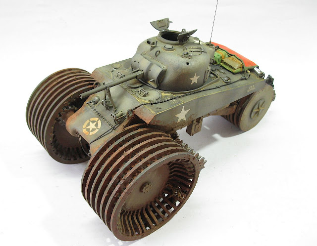
And the M4A2 T10 - Sherman T10 Mine Exploder was ready:


During the building, a colleague asked me where the ladder was, as it would be very difficult to get into the vehicle. I answered that a ladder would not be necessary, because the crew member would go up by the fork of rear wheel ... Here is the sequence of photos with the Kojak climbing the T10 !!!


As I decided to make my girl with operational markings, let's put some stuff on the rear deck: Value Gear: Always a great request !!!
 |
| Value Gear stuff...always awesome... |

 |
| Done!!! |
 |
| The rollbags painted in the rear deck... Notice the tools... |
And I asked myself: Why not make one ??

Aluminum foil and paper-tape: easy!!!
 |
| Allied air recognition panel under construction |
 |
| Allied air recognition panel in position!!! |

 |
| And another detail from the real thing: Chains!! |
 |
| M4A2 T10 - Sherman T10 Mine Exploder Operational markings - France - late1944 |


 |
| M4A2 T10 - Sherman T10 Mine Exploder with Kojak and Rover, the dog. |
 |
| At ground level ... |
 |
| Climbing on the fork ... |
 |
| After climbing on the rear wheels ... |
 |
| On the rear deck... |
 |
| Kojak manning your new toy!!! |
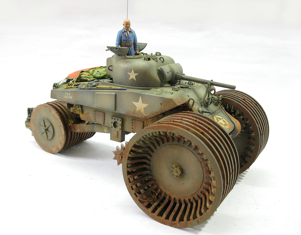 |
| M4A2 T10 - Sherman T10 Mine Exploder |
 |
| M4 Sherman T1E3 mine exploder Aunt Jemima with M4A2 T10 mine exploder, in size comparison... |

 |
| M4 Sherman T1E3 mine exploder Aunt Jemima with M4A2 T10 mine exploder |

 |
| German Minenroller, M4 Sherman T1E3Aunt Jemima and M4A2 T10 mine exploder |
 |
| German and American solutions for mines... |
 |
| M4A2 T10 mine exploder with M4A3E2 Jumbo 76mm in size comparison... |
 |
| Two specialized Shermans!!! |
The BoldDivision kit was a good kit for conversion. The best parts are the wheels, very well "thoughtful" and relatively easy to build ... One thing that could improve would be the profile of the rear of the hull. and construction instructions. End the conflicting images. But I recommend the kit ... But it's not something for beginners ...
See you soon!!!